

Finally I have done force AVR’s to read touch buttons. Atmel QTouch library was interesting, but it was too hard form me, and it’s so big. I have rode piece of teory, have found a few examples and done. First effect is this module. How does it work in practice:
How does it work in theory:
The plates touch sensors act as capacitors, loaded by a resistor. The microprocessor loads the RC circuit, measuring the time. Since R is a constant, the charging time is dependent on the capacity. Capacitance changes when attach a finger – he becomes the dielectric. For the system to work, you must take care of several elements:
–Capacity of such a “capacitor” is very small. To extend the charging time, used high-value resistors (I used the absence of other 10M, better would be about 2-5M ohms).
–One needs one pin sensor for reading, and one for loading, except that the latter may simultaneously support multiple sensors.
–Times are very small; Why does not use the delay; same rotation measurement loop is long enough.
Changes capacity are also small, so it is important to make this change after applying finger was as large as possible. Therefore, the plates have a surface in a grid, to reduce their own capacity. Contrary to intuition, the larger the field of sensors, this is not necessarily better.
–In such systems, it is important to use as the shortest path to reduce harmful capacity.
–It is also around the pouring weight, which will shield the interference and provide a second electrode of the capacitor.
–As is apparent from the above description, the measurement does not rely on the detection capacity of the human body relative to the ground, or anything like that. Human finger is dielectric of the capacitor in the electric field formed by the field of the sensor field and the nearby ground.
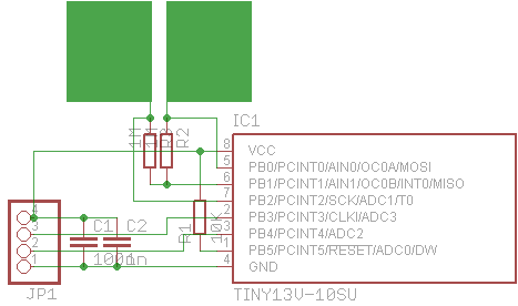
Schematic:
Download: